A wing describes the outer shape of a lifting surface. Its airfoils are placed at spanwise stations, the sections, and the surface is lofted between them. The same type describes the rotor blades of a rotorcraft (rotorBlade).
Geometry
The outer shape is built from four parts:
-
sections(wingSectionType) are coordinate systems at spanwise stations, e.g. at the root, a kink and the tip. A wing has at least two sections. -
The
elementsof a section (wingElementType) each reference an airfoil and scale, rotate and translate it within the section. Most sections have one element. -
positionings(positioningType) translate the sections by a length, a sweep angle and a dihedral angle, e.g. from one section to the next. They are optional. -
segments(wingSegmentType) each connect two elements; the surface of the wing is lofted between their airfoils.
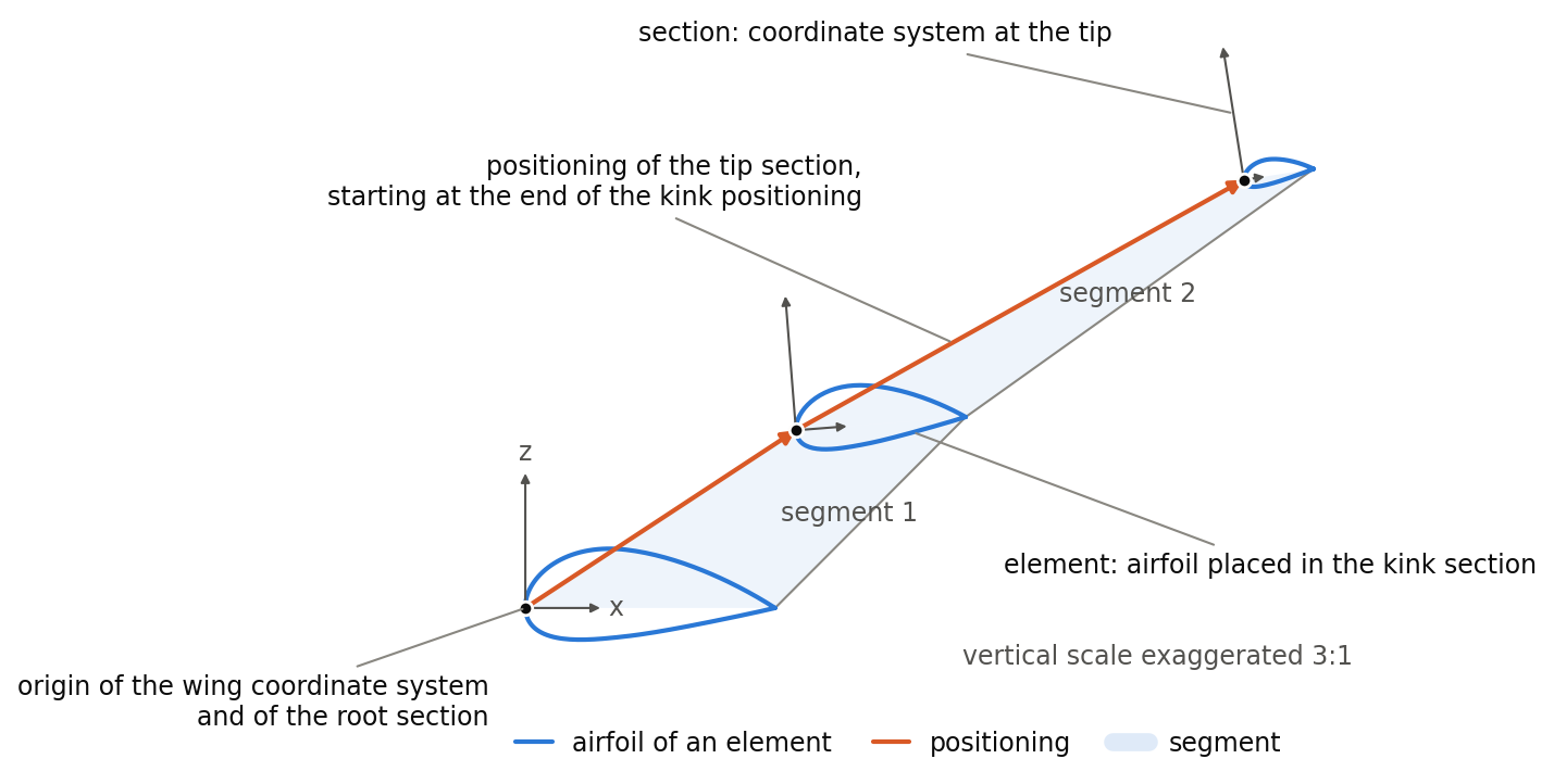
The figure shows these parts on the example wing below. Each section is a coordinate system, here at the root, the kink and the tip, and its element places an airfoil in it. The positionings lead from the root to the kink and from the kink to the tip section. The segments are the surfaces between the airfoils of neighbouring sections. The kink and tip sections are rotated about the y-axis by -1.5° and -3° (twist), so that the leading edge of their airfoils points slightly downwards; the vertical scale is exaggerated 3:1, which makes the rotation and the airfoil thickness appear larger.
Coordinate systems
A point p of an airfoil is placed in the wing coordinate system at

where Telement and Tsection are the transformations of the element and the section (transformationType), and tpositioning is the translation of the section by its positioning, or zero for a section without positioning. The positioning thus translates a section without rotating it, and a rotation of the section does not change the direction of its positioning. The transformation of the wing places the wing coordinate system in the model. A wing usually references the fuselage it is attached to with parentUID; its translation is then given relative to the position of the fuselage, so that the wing moves with it (see the local coordinate systems in cpacsType).
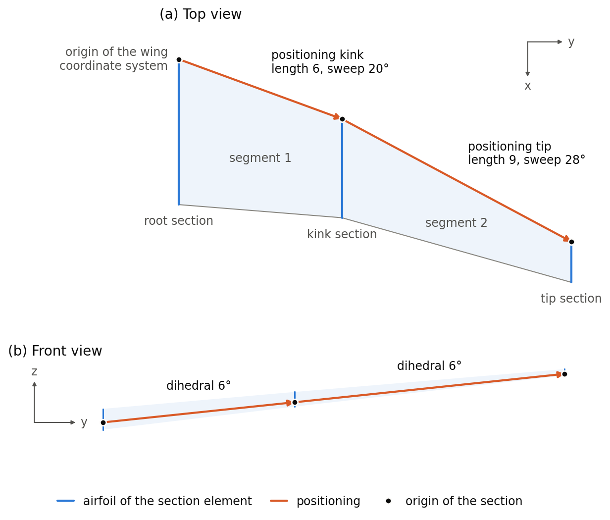
The figure shows the example below in the wing coordinate system. The root section lies at the origin. The positioning of the kink section starts there, and the positioning of the tip section starts at the end of the kink positioning, so that the sweep and dihedral of the two segments add up along the span. Each segment covers the part of the wing between two neighbouring sections.
Structure and control surfaces
Component segments (componentSegments) span one or more segments and carry the structure, the control surfaces and the wing-fuselage attachments of the wing.
Example
A wing with three sections, attached to the fuselage with parentUID and mirrored at the x-z plane. Its sections, positionings, segments and component segment are shown in the documentation of wingSectionType, positioningType, wingSegmentType and componentSegmentType. The transformations in the examples are written out in full. Since rotation and translation default to 0 and scaling to 1, rotation, translation and scaling elements with these values can be omitted to write the dataset more compactly. A scaling that is given should list all three components.
<wing uID="Wing" symmetry="x-z-plane">
    <name>Wing</name>
    <parentUID>Fuselage</parentUID>
    <transformation>
        <rotation>
            <x>0</x>
            <y>0</y>
            <z>0</z>
        </rotation>
        <scaling>
            <x>1</x>
            <y>1</y>
            <z>1</z>
        </scaling>
        <translation>
            <x>10</x>
            <y>0</y>
            <z>-0.5</z>
        </translation>
    </transformation>
    <sections>
        <section uID="Wing_root">
            ...
        </section>
        ...
    </sections>
    <positionings>
        ...
    </positionings>
    <segments>
        ...
    </segments>
    <componentSegments>
        ...
    </componentSegments>
</wing>