A component segment covers the segments of a wing from its start element (fromElementUID) to its end element (toElementUID). The structure, the control surfaces, the fuel tanks, the attachments to a fuselage or another wing and the structural mounts of the wing are defined in it, positioned by the relative coordinates η (eta) along the span and ξ (xsi) along the chord.
Rules
-
A component segment is defined like a segment, from one element to another. Unlike a segment, its start and end element do not have to be neighbours; the component segment then combines all segments in between.
-
The component segment follows the direction of its segments: starting at the start element, each of its segments begins at the element at which the previous one ends, up to the end element. The start element is therefore the inner and the end element the outer element of the component segment.
-
Each segment can only be part of one component segment. A wing therefore has at most as many component segments as segments.
-
If a section has two elements, e.g. at a step in the wing, a component segment has to start or end there, since no well-defined relative coordinates can be defined across the step.
Relative coordinates
A position in a component segment is given either in the coordinates of one of its segments or in the coordinates of the component segment. The referenceUID of the position (e.g. in etaXsiPointType or etaIsoLineType) selects the coordinates: it references either the segment or the component segment. Segment coordinates are defined on the chord surface of the segment (see wingSegmentType).
The coordinates of the component segment join the segment coordinates of its segments along the span. The elements are placed along the mid-chord line, the line through the middle points M of the chord lines of the elements. Numbering the elements from 0 at the start to n at the end element, element k lies at

where lj is the straight distance between the middle points of the chords of elements j−1 and j, measured in space, and PLE and PTE are the leading and trailing edge points of an element. η is 0 at the start element and 1 at the end element. In the component segment of the example below, the mid-chord line is 5.78 m long between the root and the kink element and 8.58 m between the kink and the tip element, so that the kink element lies at η = 5.78 / (5.78 + 8.58) = 0.403.
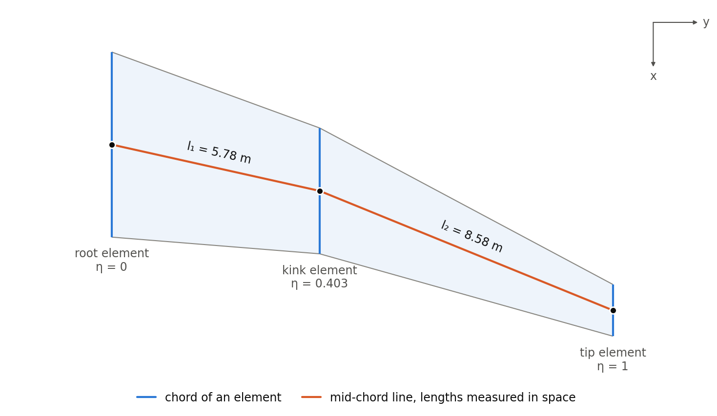
Between the elements k−1 and k, a point of the component segment is the point of the segment k in between with the coordinates

ξ is thus the same in both coordinates, and η is scaled linearly within each segment. Lines of constant η run straight from the leading to the trailing edge; lines of constant ξ are straight within each segment and bend at the elements. To find the point with given η and ξ, go to η on the mid-chord line and then along the line of constant η to ξ.
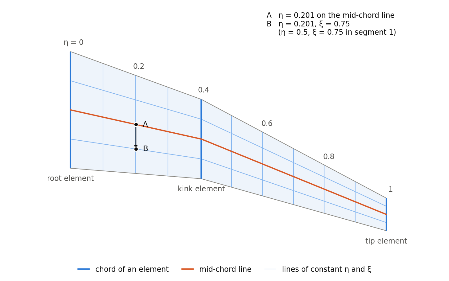
The figure shows the lines of constant η and ξ of the component segment of the example below. The point B with η = 0.201 and ξ = 0.75 is found at A, η = 0.201 on the mid-chord line, and then along the line of constant η; in the coordinates of segment 1, it is the point with η = 0.5 and ξ = 0.75.
Example
The component segment of the wing shown in wingType, from the root to the tip element:
<componentSegments>
    <componentSegment uID="Wing_componentSegment">
        <name>Component segment</name>
        <fromElementUID>Wing_root_element</fromElementUID>
        <toElementUID>Wing_tip_element</toElementUID>
    </componentSegment>
</componentSegments>The two spar positions below describe the point of the figure, once in the coordinates of the component segment and once in the coordinates of segment 1; they differ only by the rounding of η:
<sparPositions>
    <sparPosition uID="Wing_sparPosition_componentSegment">
        <sparPositionEtaXsi>
            <eta>0.2013</eta>
            <xsi>0.75</xsi>
            <referenceUID>Wing_componentSegment</referenceUID>
        </sparPositionEtaXsi>
    </sparPosition>
    <sparPosition uID="Wing_sparPosition_segment">
        <sparPositionEtaXsi>
            <eta>0.5</eta>
            <xsi>0.75</xsi>
            <referenceUID>Wing_segment1</referenceUID>
        </sparPositionEtaXsi>
    </sparPosition>
</sparPositions>