A segment connects the airfoil of its start element (fromElementUID) with the airfoil of its end element (toElementUID), and the surface of the wing is lofted between them. The segments of a wing follow each other from root to tip; usually, each segment starts at the element at which the previous one ends. Guide curves (guideCurveType) can shape the surface between the airfoils.
Segment coordinates
Positions on a segment, e.g. of spars, ribs or control surfaces, are given in the relative coordinates η (eta) along the span and ξ (xsi) along the chord. They are defined on the chord surface of the segment, the surface between the chord lines of its start and end element. A chord line runs from the leading to the trailing edge of the airfoil as it is placed in the wing, so that a point with the coordinates η and ξ lies at
![P(eta, xsi) = (1 - eta) [(1 - xsi) P_LE,from + xsi P_TE,from] + eta [(1 - xsi) P_LE,to + xsi P_TE,to]](../../media/equations/segmentEtaXsi.png)
where PLE and PTE are the leading and trailing edge points of the start element (from) and the end element (to). η runs from 0 at the start element to 1 at the end element, and ξ from 0 at the leading edge to 1 at the trailing edge. Lines of constant η and lines of constant ξ are straight. The points lie on the chord surface, not on the upper or lower surface of the wing; guide curves do not change them. Component segments (componentSegmentType) combine the coordinates of several segments.
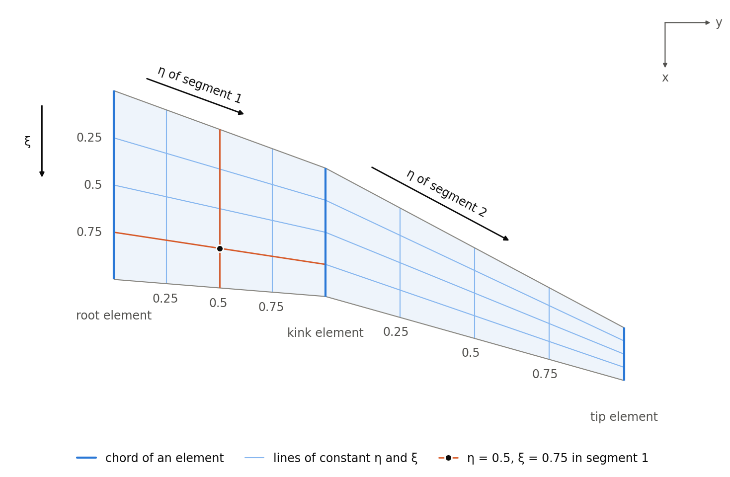
The figure shows the coordinates of the two segments of the example below in the top view. Each segment has its own coordinates from 0 to 1. The marked point lies halfway between the root and the kink element (η = 0.5) at three quarters of the chord (ξ = 0.75) of segment 1.
Example
The segments of the wing shown in wingType, from the root to the kink section and from the kink to the tip section:
<segments>
    <segment uID="Wing_segment1">
        <name>Segment 1</name>
        <fromElementUID>Wing_root_element</fromElementUID>
        <toElementUID>Wing_kink_element</toElementUID>
    </segment>
    <segment uID="Wing_segment2">
        <name>Segment 2</name>
        <fromElementUID>Wing_kink_element</fromElementUID>
        <toElementUID>Wing_tip_element</toElementUID>
    </segment>
</segments>