A fuselage describes the outer shape of a body along its x-axis. Its profiles are placed at stations along the axis, the sections, and the surface is lofted through them. The structure, the cabin, the fuel tanks and the cut-outs of the fuselage refer to this geometry.
Geometry
The outer shape is built from the same four parts as that of a wing (wingType):
-
<sections>(fuselageSectionType) are coordinate systems at stations along the x-axis, e.g. at the nose, along the cabin and at the tail. A fuselage has at least two sections. -
The
<elements>of a section (fuselageElementType) each reference a profile in the y-z plane and scale, rotate and translate it within the section, e.g. to the width and height of the fuselage at that station. Most sections have one element. -
<positionings>(positioningType) translate the sections by a length and two angles; with a sweep angle of 90°, a positioning points along the x-axis. They are optional. -
<segments>(fuselageSegmentType) each connect two elements; the surface of the fuselage is lofted through their profiles.
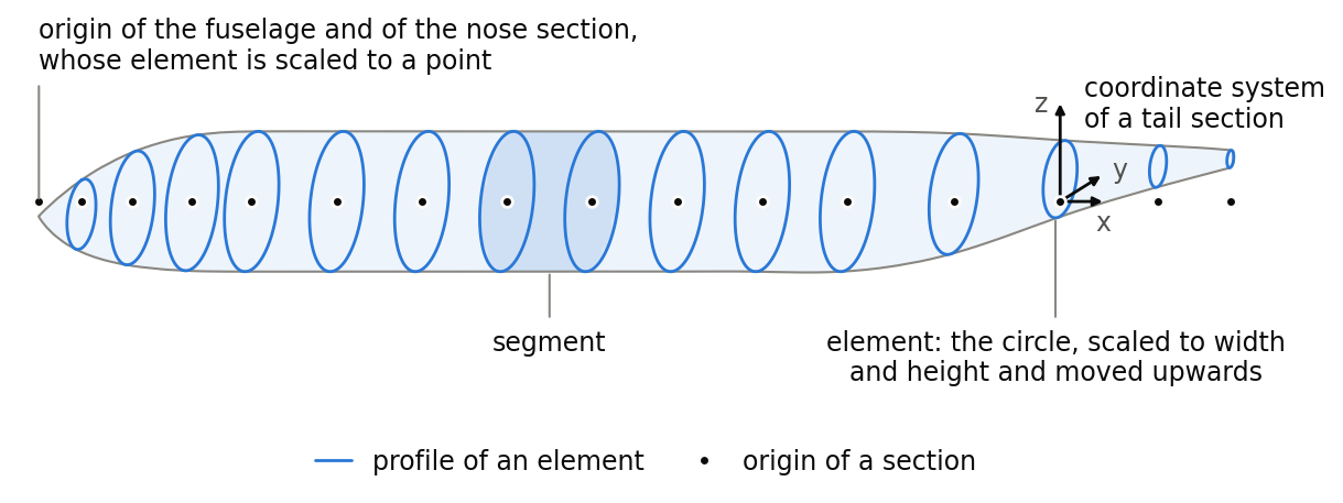
The figure shows these parts on the example fuselage below. Each section is a coordinate system on the x-axis, and its element places a circle in it, scaled to the width and height of the fuselage at that station. The element of the nose section is scaled to a point, and the elements of the tail sections are moved upwards. A segment is the part of the surface between the profiles of two neighbouring sections.
Coordinate systems
A point p of a profile is placed in the fuselage coordinate system at

where Telement and Tsection are the transformations of the element and the section (transformationType), and tpositioning is the translation of the section by its positioning, or zero for a section without positioning. This is the same placement as for the airfoils of a wing. The transformation of the fuselage places the fuselage coordinate system in the model. Wings, tanks and other components usually reference the fuselage with <parentUID>, so that they move with it (see the local coordinate systems in cpacsType).
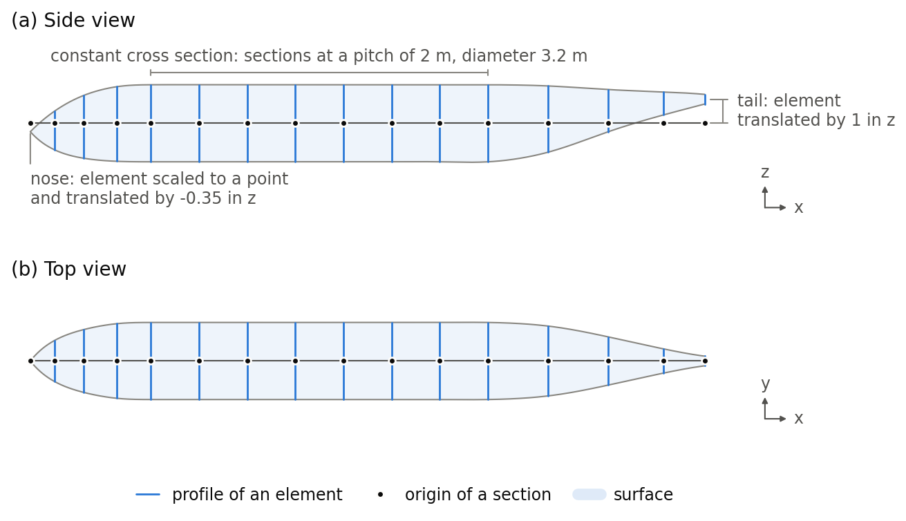
The figure shows the example below in the side and the top view. The sections lie on the x-axis, from the nose at the origin to the tail at x = 28 m. Along the cabin, they follow at a pitch of 2 m with the same circle of diameter 3.2 m. The element of the pointed nose is moved slightly downwards, and those of the tail upwards to a small end profile.
Surface
The surface of a fuselage is lofted through the profiles of all its segments as one surface, continuous in curvature across the sections (@loftContinuity C2, the default). It passes through every profile, and its shape between two sections also depends on the neighbouring sections. A part of constant cross section, such as the cabin, therefore stays constant only where its sections follow at a close pitch.
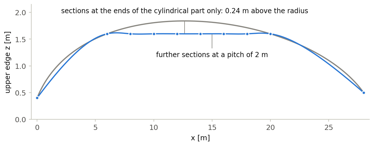
The figure shows the upper edge of a simple fuselage in the side view, with sections of the same circle at the ends of its cylindrical part. With no sections in between, the surface bulges out above the radius of the sections, because it also runs smoothly through the sections at the nose and the tail. Further sections of the same circle at a pitch of 2 m keep the upper edge at the radius. The fuselage is an illustration.
Structure, cabin and tanks
The structure (fuselageStructureType), the compartments and decks of the cabin (compartmentsType, decksType), the fuel tanks (fuselageFuelTanksType) and the cut-outs (fuselageCutOutsType) of the fuselage are described in their own types.
Example
The fuselage of a short-range airliner, 28 m long, with sixteen sections placed along the x-axis by their translation. Its sections, elements and segments are shown in the documentation of fuselageSectionType, fuselageElementType and fuselageSegmentType. The transformations in the examples are written out in full; <rotation>, <translation> and <scaling> elements with their default values can be omitted (transformationType).
<fuselage uID="Fuselage">
    <name>Fuselage</name>
    <transformation>
        <rotation>
            <x>0</x>
            <y>0</y>
            <z>0</z>
        </rotation>
        <scaling>
            <x>1</x>
            <y>1</y>
            <z>1</z>
        </scaling>
        <translation>
            <x>0</x>
            <y>0</y>
            <z>0</z>
        </translation>
    </transformation>
    <sections>
        <section uID="Fuselage_nose">
            ...
        </section>
        ...
    </sections>
    <segments>
        ...
    </segments>
</fuselage>