A guide curve runs along the surface of a wing or fuselage segment, from a point on the start profile to a point on the end profile of the segment. The surface is lofted through the profiles and the guide curves together, so that guide curves control the shape between the sections, e.g. a curved leading edge, a canopy or a smooth transition over a kink, without additional sections. The shape of the curve is taken from a guide curve profile (guideCurveProfileUID), a list of points in relative coordinates that several guide curves can share.
Start and end point
fromRelativeCircumference places the start point on the start profile of the segment (fromElementUID), toRelativeCircumference the end point on the end profile (toElementUID). The relative circumference is the arc length along the profile in the direction of its points, as a fraction of the profile length: on a wing profile, it runs from -1 at the trailing edge of the lower side over 0 at the leading edge to 1 at the trailing edge of the upper side, each side counting for 1; on a fuselage profile, it runs from 0 at the first point, the highest point, downwards along the side of positive y, so that the lowest point of a full, mirror-symmetric profile lies at 0.5.
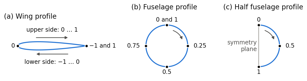
Instead of the relative circumference, fromParameter and toParameter give the curve parameter of the profile, which runs from 0 at the first to 1 at the last point and can be fixed at selected points by a parameterMap (curvePointListXYZType). This places a guide curve exactly on a profile point with a fixed parameter, e.g. a kink, independently of the arc length.
Shape between start and end point
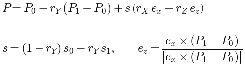
The points of the guide curve profile are given relative to the straight line from the start point P0 to the end point P1. rY is the position along this line, rX and rZ are offsets from it, scaled by the size of the profiles. A point of the guide curve is
-
ex is the unit vector along
rXDirection. By default, it is the x-axis of the wing, i.e. along the chord towards the trailing edge, or the z-axis of the fuselage, i.e. upwards. -
ez is normal to ex and to the line from P0 to P1. With the default directions, it points upwards on a wing that extends towards positive y, and towards positive y on a fuselage that extends towards positive x.
-
s0 and s1 are the chord lengths (wing) or heights (fuselage) of the start and end profile as placed in the component, i.e. including all scalings. Along the guide curve, the scale s changes linearly between them.
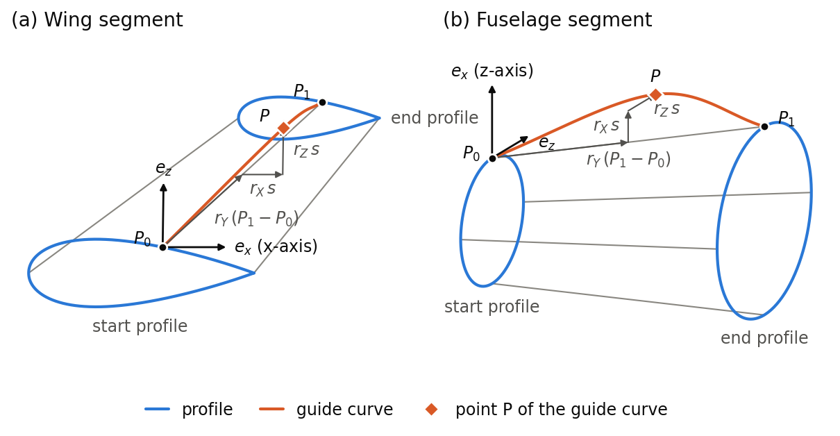
Figure (a) constructs the point P of a guide curve on the upper side of a wing: rY = 0.5 leads to the middle of the line from P0 to P1, rX moves the point towards the trailing edge and rZ upwards. Figure (b) shows the same construction for a guide curve on top of a fuselage, where rX moves the point upwards and rZ sideways. A guide curve profile with rX and rZ equal to 0 gives a straight guide curve.
Guide curves over several segments
A guide curve ends at the end profile of its segment. In the next segment, it is continued by a guide curve that references it with fromGuideCurveUID instead of giving a start point; the continuing curve starts where the referenced curve ends. Connected in this way, the guide curves of all segments form one curve along the whole component. Only the guide curves of the first segment give their start point explicitly.
continuity describes how a continuing curve joins the referenced curve at the common section:
| continuity | Transition at the section |
| not given | Smooth. The connected guide curves form a single curve through all their points. |
C0 | The curves only share the point, so the transition may have a kink. Each curve is shaped by its own points only. |
C1 from previous, C2 from previous | This curve starts with the tangent (C1) or also with the curvature (C2) with which the referenced curve ends. The referenced curve is not affected. |
C1 to previous, C2 to previous | The other way round: the referenced curve ends with the tangent (C1) or also with the curvature (C2) with which this curve starts. |
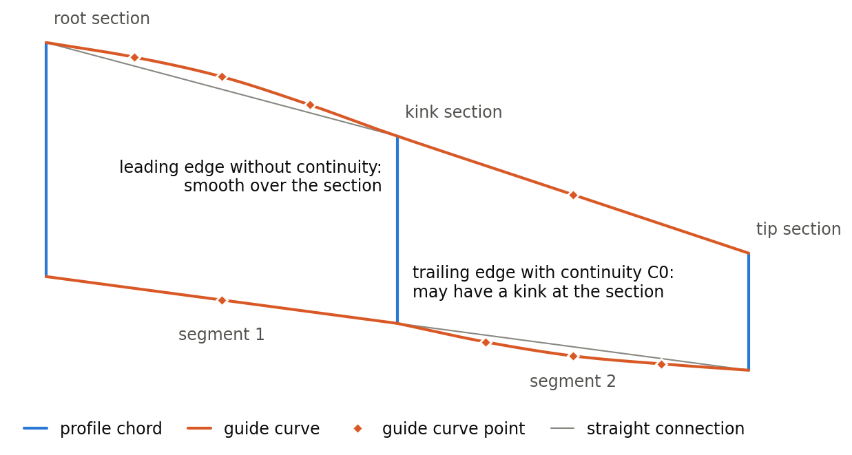
The figure shows the planform of the example below. The leading edge guide curve of the outer segment has no continuity, so the leading edge stays smooth over the kink section although only the inner segment is curved. The trailing edge guide curve of the outer segment has continuity C0: it is curved while the inner one is straight, and the trailing edge has a kink at the section.
The optional tangent elements prescribe the tangent of the guide curve at its start point (only for a guide curve with an explicit start point) and at its end point, e.g. to let a fuselage start parallel to its axis.
Requirements
-
Every guide curve is continued over all segments of the component, i.e. all segments have the same number of guide curves.
-
Guide curves and profiles form a valid curve network: each guide curve meets each profile exactly once, and guide curves neither cross nor touch each other.
Example
The following wing has three sections (root, kink, tip). The excerpt shows the guide curves of the leading edge and of the upper side of the trailing edge; the guide curves of the lower side of the trailing edge follow the same pattern with relative circumference -1. Of the referenced guide curve profiles (guideCurveProfileGeometryType), GCP_straight gives straight guide curves, while GCP_leadingEdgeBulge and GCP_trailingEdgeBulge move the middle of the curve forward or backward by up to 6 % of the local chord.
<segments>
    <segment uID="GuideCurveWing_segment1">
        <name>Segment 1</name>
        <fromElementUID>GuideCurveWing_root_element</fromElementUID>
        <toElementUID>GuideCurveWing_kink_element</toElementUID>
        <guideCurves>
            <guideCurve uID="GuideCurveWing_leadingEdge_1">
                <name>Leading edge, segment 1</name>
                <guideCurveProfileUID>GCP_leadingEdgeBulge</guideCurveProfileUID>
                <fromRelativeCircumference>0</fromRelativeCircumference>
                <toRelativeCircumference>0</toRelativeCircumference>
            </guideCurve>
            <guideCurve uID="GuideCurveWing_trailingEdgeUpper_1">
                <name>Trailing edge, upper side, segment 1</name>
                <guideCurveProfileUID>GCP_straight</guideCurveProfileUID>
                <fromRelativeCircumference>1</fromRelativeCircumference>
                <toRelativeCircumference>1</toRelativeCircumference>
            </guideCurve>
            ...
        </guideCurves>
    </segment>
    <segment uID="GuideCurveWing_segment2">
        <name>Segment 2</name>
        <fromElementUID>GuideCurveWing_kink_element</fromElementUID>
        <toElementUID>GuideCurveWing_tip_element</toElementUID>
        <guideCurves>
            <guideCurve uID="GuideCurveWing_leadingEdge_2">
                <name>Leading edge, segment 2</name>
                <guideCurveProfileUID>GCP_straight</guideCurveProfileUID>
                <fromGuideCurveUID>GuideCurveWing_leadingEdge_1</fromGuideCurveUID>
                <toRelativeCircumference>0</toRelativeCircumference>
            </guideCurve>
            <guideCurve uID="GuideCurveWing_trailingEdgeUpper_2">
                <name>Trailing edge, upper side, segment 2</name>
                <guideCurveProfileUID>GCP_trailingEdgeBulge</guideCurveProfileUID>
                <fromGuideCurveUID>GuideCurveWing_trailingEdgeUpper_1</fromGuideCurveUID>
                <continuity>C0</continuity>
                <toRelativeCircumference>1</toRelativeCircumference>
            </guideCurve>
            ...
        </guideCurves>
    </segment>
</segments>