The detailed center fuselage area of a low-wing transport aircraft: the wing box passes through the fuselage below the cabin floor, and the bay of the main landing gear follows directly behind it. The definition describes the parts that carry the loads around this cut-out of the shell.
Parts
-
<centerFuselageMainFrames>: three main frames bound the area, the first and the second at the front and the rear spar of the wing box, the third at the rear end of the bay. Flat pressure bulkheads at the first and the third separate the pressurised cabin from the wing box and the bay. -
<centerFuselagePressureFloor>: the horizontal pressure boundary over the bay, between the second and the third main frame. -
<centerFuselageSidebox>: box-shaped longitudinal reinforcements on both sides of the bay, between the pressure floor and the skin, from the rear spar to the third main frame; the pressure floor ends at them. -
<centerFuselageLateralPanels>: triangular panels on each side that connect the side boxes to the rear spar. -
<centerFuselageKeelbeam>: a box-shaped beam along the bottom from the first to the third main frame that carries the bending of the fuselage across the cut-out, with triangular ends that lead the loads into the skin. -
<centerFuselageLongFloorBeamsConnection>: the connection of the longitudinal floor beams to the pressure floor, a simplified representation of the portal frames.
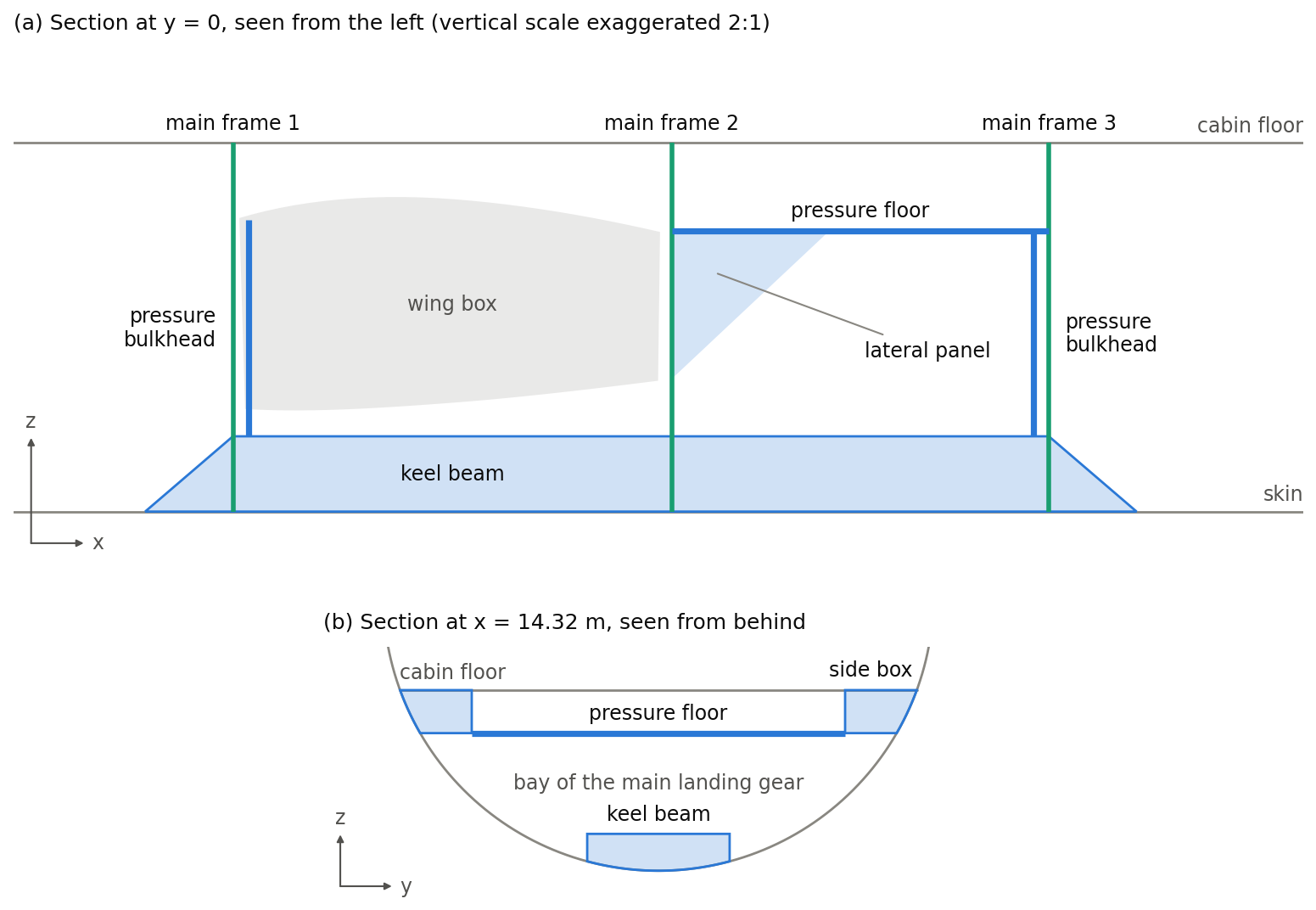
The figure illustrates the parts in the fuselage of the examples, with the main frames at the spars of the wing at x = 10.75 m and 13.25 m and at the end of the bay at x = 15.4 m. It shows the layout, not the parameters: the sizes of the parts are chosen for the illustration.
How several parameters of the parts are to be read is not specified yet; the pages of the parts say which.
Rules
-
The first and the second main frame lie at the front and the rear spar of the wing box where it passes through the fuselage.
-
A stringer that gives a height, of the pressure floor or of the keel beam, runs at a constant height along the area.