Logical view of a system: which components are connected, and by what kind of connection. The physical description in genericSystems says which elements are installed and where; the architecture adds the connections between the components and to other systems. What a connection carries in a given flight condition is stated in powerBreakdowns.
In the top-down approach of CPACS, an architecture can first be declared by its <systemType> alone, i.e. by an ATA chapter or as generic, and the connections are added as the design matures.
connections holds the connections of the system, each directed from a source to a target.
controlDevices make the whole architecture switchable, e.g. a backup system that is only active after a failure; a static power breakdown case sets its state.
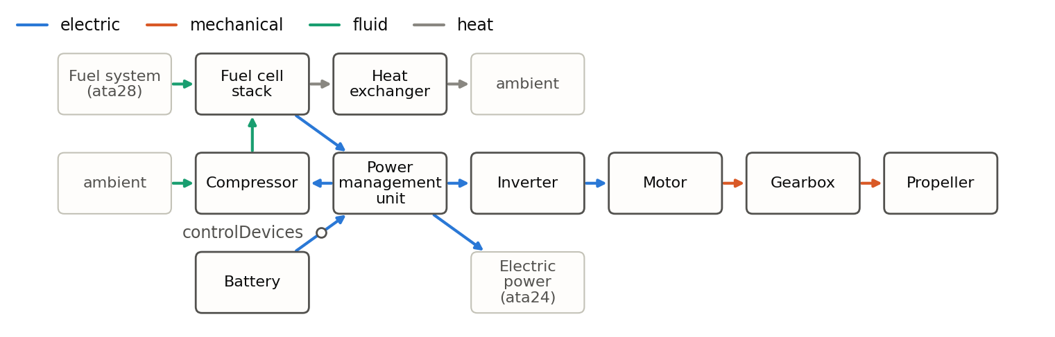
The figure shows the architecture of one propulsion unit of a regional aircraft with hydrogen fuel cells. Its topology follows the propulsion unit of the ESBEF-CP1 concept aircraft in Burschyk et al., Introduction of a System Definition in CPACS, Aerospace 12 (2025) 373 in section 4.2; the dimensions, masses and power values are illustrative. A fuel cell stack and a battery deliver electric power to a power management unit, which supplies the electric power train, the compressor of the air supply and the electrical power supply system of the aircraft. A heat exchanger takes the waste heat of the fuel cell to the ambient air, along two connections of the type heat. The connection from the battery has a control device, so that a case can switch the battery on or off. Outside the unit, the connections end at the ambient and at two systems that are known only by their ATA chapter, the fuel system and the electrical power supply.
Part of this architecture: the connections from the fuel cell stack and from the battery to the power management unit, the latter with its control device, from the power management unit to the electrical power supply (ata24), and from the ambient to the compressor:
<systemArchitecture uID="propulsionUnit_pod1">
    <name>Propulsion unit, pod 1</name>
    <systemType>generic</systemType>
    <connections>
        <connection uID="fuelCellToPmu_pod1">
            <name>Fuel cell stack to power management unit</name>
            <connectionType>electric</connectionType>
            <source>
                <componentUID>fuelCellStack_pod1</componentUID>
            </source>
            <target>
                <componentUID>pmu_pod1</componentUID>
            </target>
        </connection>
        <connection uID="batteryToPmu_pod1">
            <name>Battery to power management unit</name>
            <connectionType>electric</connectionType>
            <controlDevices uID="batteryContactor_pod1">
                <state>
                    <controlParameterActive>1</controlParameterActive>
                    <controlParameterInactive>0</controlParameterInactive>
                </state>
            </controlDevices>
            <source>
                <componentUID>battery_pod1</componentUID>
            </source>
            <target>
                <componentUID>pmu_pod1</componentUID>
            </target>
        </connection>
        <connection uID="pmuToEpss_pod1">
            <name>Power management unit to the electrical power supply system</name>
            <connectionType>electric</connectionType>
            <source>
                <componentUID>pmu_pod1</componentUID>
            </source>
            <target>
                <ataChapter>ata24</ataChapter>
            </target>
        </connection>
        <connection uID="airIntake_pod1">
            <name>Air intake</name>
            <connectionType>fluid</connectionType>
            <source>
                <externalElement>ambient</externalElement>
            </source>
            <target>
                <componentUID>compressor_pod1</componentUID>
            </target>
        </connection>
        ...
    </connections>
</systemArchitecture>