A power breakdown gives the power that flows through the systems of the vehicle in a flight condition: the mass flow, heat flow, electric power and mechanical power that the connections of the system architectures carry. It is the analysis level of the system description: each flow references a connection of a system architecture (systemArchitecturesType). The ends of a connection are installed system components (genericSystemsType), other parts of the vehicle such as a fuselage, a wing or a fuel tank, other systems, or external elements such as the ambient.
Static and transient cases
A static case holds the flows at one flight condition, given by altitude and speed or by a flight point (staticCaseType). A transient case holds them along a trajectory: each value is a vector with one entry per flight point of the trajectory (transientCaseType). A static case also gives the state of the switchable parts of the systems in its configuration (systemControlDevicesType).
Power flows
A power flow belongs to one of four categories, each with its own value:
-
<massFlow>: mass flow of a medium [kg/s], optionally with its pressure, temperature and composition, -
<heatFlow>: heat flow [W], optionally with the temperatures of source and sink, -
<electricPower>: electric power [W], optionally with the voltage of a direct current or the characteristics of an alternating current, -
<mechanicalPower>: mechanical power [W], optionally with a torque or a force.
Rules
-
A power flow references a connection with
<connectionUID>and flows in its direction, from the<source>to the<target>of the connection. -
Several power flows of a case may reference the same connection, at most one per category.
-
There is no explicit element for losses. A loss can be marked as a heat flow, e.g. the waste heat that a component gives off to a cooling system or to the ambient, as for the fuel cell in the example below; otherwise the losses of a component follow from the balance of its incoming and outgoing flows.
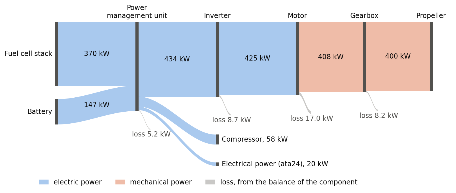
The figure shows the electric and mechanical power flows at take-off of the propulsion unit whose architecture is shown for systemArchitectureType. The fuel cell stack and the battery deliver 517 kW to the power management unit, of which 400 kW reach the propeller as shaft power. The losses drawn are not part of the data; they follow from the balance of each component, e.g. 17.0 kW at the motor, which takes 425 kW and delivers 408 kW. The mass flows and heat flows of the same case are not drawn. The values illustrate the data and are derived from typical efficiencies; they are not those of the study the architecture is taken from.
One flow of each category of this case, and the specification of the case, which switches the battery on through the control device of its connection:
<powerBreakdowns>
    <staticCases>
        <staticCase uID="takeOff">
            <name>Take-off</name>
            <specification>
                <altitude>0</altitude>
                <machNumber>0.2</machNumber>
                <environment>
                    <atmosphericModel>ISA</atmosphericModel>
                </environment>
                <configuration>
                    <controlElements>
                        <controlElement>
                            <controlDeviceUID>batteryContactor_pod1</controlDeviceUID>
                            <controlParameter>1</controlParameter>
                        </controlElement>
                    </controlElements>
                </configuration>
            </specification>
            <powerBreakdownData>
                <powerFlow>
                    <name>Battery to power management unit</name>
                    <connectionUID>batteryToPmu_pod1</connectionUID>
                    <electricPower>
                        <electricPowerValue>147100</electricPowerValue>
                        <directCurrent>800</directCurrent>
                    </electricPower>
                </powerFlow>
                <powerFlow>
                    <name>Motor shaft</name>
                    <connectionUID>motorShaft_pod1</connectionUID>
                    <mechanicalPower>
                        <mechanicalPowerValue>408200</mechanicalPowerValue>
                        <torque>649.6</torque>
                    </mechanicalPower>
                </powerFlow>
                <powerFlow>
                    <name>Compressed air</name>
                    <connectionUID>airSupply_pod1</connectionUID>
                    <massFlow>
                        <massFlowValue>0.4221</massFlowValue>
                        <singlePhaseMassFlow>
                            <pressure>253300</pressure>
                            <temperature>411.3</temperature>
                            <massComposition>
                                <species>
                                    <share>1</share>
                                    <type>Air</type>
                                </species>
                            </massComposition>
                        </singlePhaseMassFlow>
                    </massFlow>
                </powerFlow>
                <powerFlow>
                    <name>Coolant loop</name>
                    <connectionUID>coolantLoop_pod1</connectionUID>
                    <heatFlow>
                        <heatFlowValue>370000</heatFlowValue>
                        <sourceTemperature>353.15</sourceTemperature>
                        <sinkTemperature>343.15</sinkTemperature>
                    </heatFlow>
                </powerFlow>
                ...
            </powerBreakdownData>
        </staticCase>
    </staticCases>
</powerBreakdowns>