A structural profile is the cross section of a beam-like structural part, e.g. of a stringer, a frame or a floor beam. It consists of points and of sheets that connect them. A profile-based structural element (profileBasedStructuralElementType) references the profile by its uID, assigns a material and a thickness to each sheet (sheetProperties) and can add reinforcements at single points (pointProperties). The structural part that uses the element extends the cross section along its axis.
Points and sheets
-
The points lie in the x-y plane of the profile. Their coordinates are lengths in metres. The z-axis of the profile is normal to this plane and runs along the axis of the structural part.
-
A sheet connects the point
fromPointUIDwith the pointtoPointUID. Every point used by a sheet or by the structural element therefore needs auID. -
Several sheets can meet in one point. Open cross sections (e.g. L, T or Z) and closed ones (e.g. a box) are built in the same way.
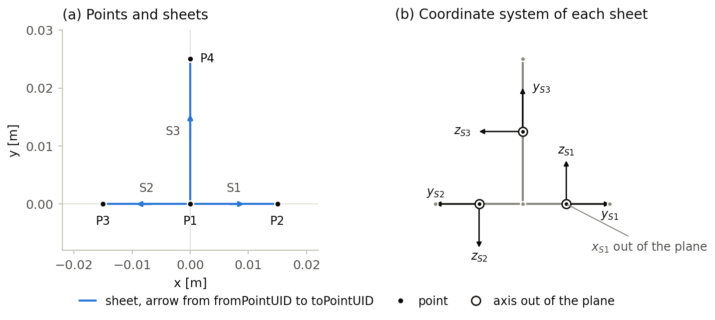
Figure (a) shows the profile of the example below; the labels omit the prefix TStringerProfile_ of the uID. All three sheets start at the point P1, where they meet.
Coordinate system of a sheet
Each sheet has its own right-handed coordinate system, which follows from the direction of the sheet (figure b):
-
yS points along the sheet from
fromPointUIDtotoPointUID. -
zS is normal to the sheet and lies in the profile plane: it is yS rotated by +90° about the z-axis of the profile. The thickness of the sheet is measured along zS and lies symmetrically about the line connecting the two points.
-
xS = yS × zS is normal to the profile plane, i.e. parallel to the z-axis of the profile, and runs along the structural part.
Swapping fromPointUID and toPointUID reverses yS and zS of the sheet. The orthotropy direction of a composite (orthotropyDirection in sheetProperties) is the xS-axis rotated by the given angle about zS; a positive angle turns it towards yS.
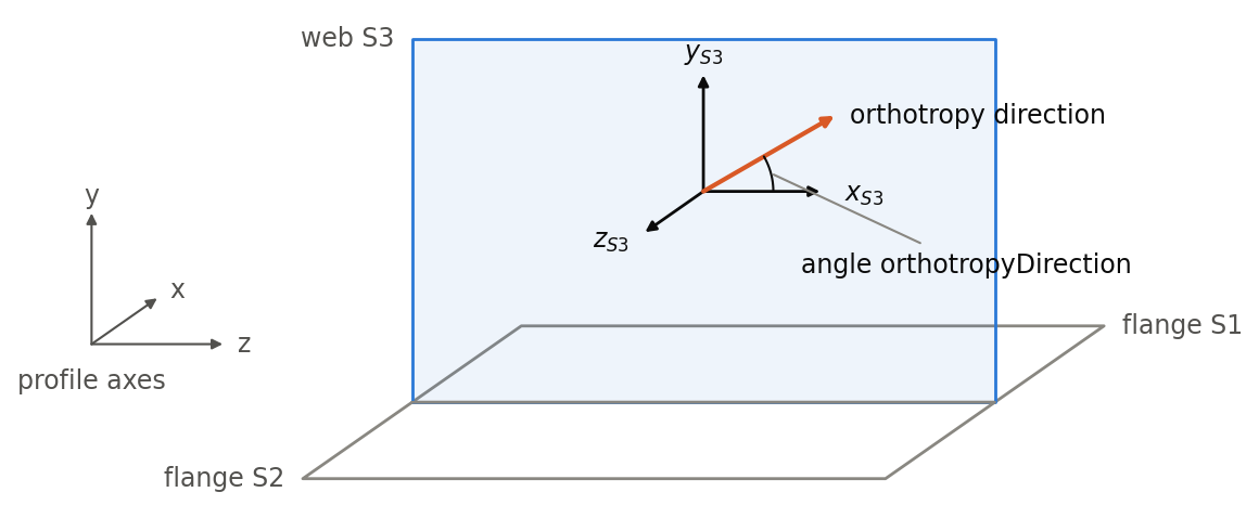
The figure shows the web S3 of the example as a surface along the structural part, with its coordinate system and the orthotropy direction for an angle of 30°.
Example
A T-shaped stringer profile with a flange of 30 mm width and a web of 25 mm height:
<structuralProfile2D uID="TStringerProfile">
    <name>T-stringer</name>
    <description>Flange of 30 mm and web of 25 mm height</description>
    <pointList>
        <point uID="TStringerProfile_P1">
            <x>0</x>
            <y>0</y>
        </point>
        <point uID="TStringerProfile_P2">
            <x>0.015</x>
            <y>0</y>
        </point>
        <point uID="TStringerProfile_P3">
            <x>-0.015</x>
            <y>0</y>
        </point>
        <point uID="TStringerProfile_P4">
            <x>0</x>
            <y>0.025</y>
        </point>
    </pointList>
    <sheetList>
        <sheet uID="TStringerProfile_S1">
            <name>Right flange</name>
            <fromPointUID>TStringerProfile_P1</fromPointUID>
            <toPointUID>TStringerProfile_P2</toPointUID>
        </sheet>
        <sheet uID="TStringerProfile_S2">
            <name>Left flange</name>
            <fromPointUID>TStringerProfile_P1</fromPointUID>
            <toPointUID>TStringerProfile_P3</toPointUID>
        </sheet>
        <sheet uID="TStringerProfile_S3">
            <name>Web</name>
            <fromPointUID>TStringerProfile_P1</fromPointUID>
            <toPointUID>TStringerProfile_P4</toPointUID>
        </sheet>
    </sheetList>
</structuralProfile2D>The structural element assigns a thickness of 1.6 mm to the right flange and adds a stiffener of 20 mm² cross section at the tip of the web:
<profileBasedStructuralElement uID="TStringer">
    <name>T-stringer</name>
    <sheetProperties>
        <sheetUID>TStringerProfile_S1</sheetUID>
        <materialUID>Aluminium2024</materialUID>
        <thickness>0.0016</thickness>
    </sheetProperties>
    ...
    <structuralProfileUID>TStringerProfile</structuralProfileUID>
    <pointProperties>
        <pointUID>TStringerProfile_P4</pointUID>
        <materialUID>Aluminium2024</materialUID>
        <crossSectionArea>2e-05</crossSectionArea>
    </pointProperties>
</profileBasedStructuralElement>