A standard profile describes the cross section of a fuselage-like body by a few parameters instead of a point list: either a rectangle with optionally rounded corners or a superellipse. It is intended for fuselage profiles.
Coordinates
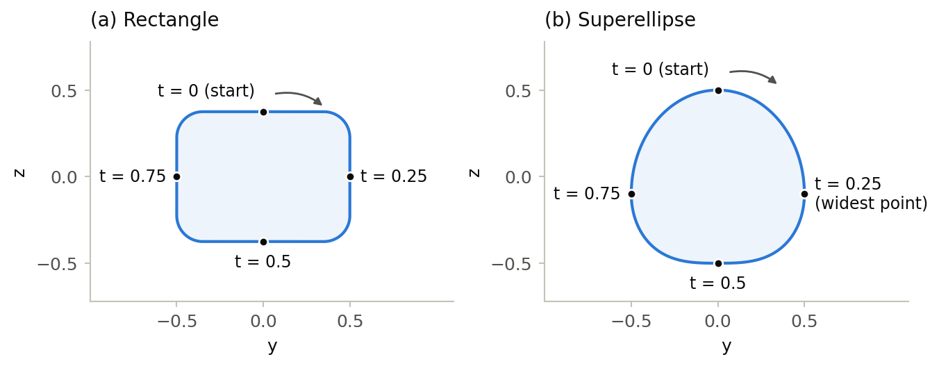
The profile is a closed curve in the y-z plane (x = 0), centered at the origin. Its width in y direction is always 1; its height in z direction is 1 for a superellipse and heightToWidthRatio for a rectangle. The actual size, position and orientation are defined where the profile is referenced, e.g. by the scaling of a fuselage element; scaling y and z differently changes the proportions of the profile.
Order and curve parameter
Start point, direction and curve parameter t of a standard profile are not set in the data, but they determine how it is used: points with equal parameters of consecutive profiles are connected (see Combining profiles below), and positions on the profile, such as the start and end of a fuselage guide curve (guideCurveType), are counted from the start point in the direction of the curve.
The curve starts at the top (y = 0) and runs first over the positive y side down to the bottom and then over the negative y side back to the top. Its curve parameter t runs from 0 to 1, and four points have fixed parameters:
| t | Rectangle | Superellipse |
| 0 and 1 | middle of the upper side | top |
| 0.25 | middle of the side at y = 0.5 | widest point at y = 0.5 |
| 0.5 | middle of the lower side | bottom |
| 0.75 | middle of the side at y = −0.5 | widest point at y = −0.5 |
How the parameter is distributed between these points is left to the tool.
Combining profiles
Consecutive profiles of a fuselage are connected at equal curve parameters (see curvePointListXYZType). Between two standard profiles, top, sides and bottom are therefore always connected with each other, even if the profiles differ in type or proportions. Fuselage point lists follow the same order (see profileGeometryType), so that both can be combined in one fuselage. The corresponding points of a point list can be given the parameters 0.25, 0.5 and 0.75 with a parameterMap.
Example
The following fuselage profiles are the rectangle and the superellipse shown in the figure above.
<fuselageProfiles>
    <fuselageProfile uID="RectangleProfile">
        <name>Rectangle with rounded corners</name>
        <standardProfile>
            <rectangle>
                <cornerRadius>0.15</cornerRadius>
                <heightToWidthRatio>0.75</heightToWidthRatio>
            </rectangle>
        </standardProfile>
    </fuselageProfile>
    <fuselageProfile uID="SuperEllipseProfile">
        <name>Superellipse with flattened lower half</name>
        <standardProfile>
            <superEllipse>
                <mUpper>2</mUpper>
                <nUpper>2</nUpper>
                <mLower>3</mLower>
                <nLower>2</nLower>
                <lowerHeightFraction>0.4</lowerHeightFraction>
            </superEllipse>
        </standardProfile>
    </fuselageProfile>
</fuselageProfiles>