Profiles are the cross sections of wings and other wing-like components (wingAirfoils), of rotor blades (rotorAirfoils) and of fuselages and other fuselage-like bodies (fuselageProfiles). The elements of a component's sections reference a profile by its uID and scale, rotate and position it.
Representations
The geometry of a profile is given by exactly one of the following representations:
| Element | Geometry | Intended for |
pointList | smooth curve through an ordered list of points, optionally with kinks, fixed curve parameters or approximation (see curvePointListXYZType) | all profiles |
cst2D | airfoil defined analytically by the class-shape transformation (see cst2DType) | wing and rotor airfoils |
nacaProfile | airfoil defined by a NACA 4-digit or 5-digit code (see nacaProfileType) | wing and rotor airfoils |
standardProfile | rectangle with optionally rounded corners or superellipse (see standardProfileType) | fuselage profiles |
The remarks below on coordinates and point order apply to point lists; the other representations define them in their own documentation.
Coordinates
A profile is defined in its own coordinate system; the referencing element and section transform it into the coordinate system of the component. All three coordinate vectors of a point list are mandatory, but one of them contains only zeros: wing and rotor airfoils lie in the x-z plane, fuselage profiles in the y-z plane. Normalized coordinates are not required. Wing and rotor airfoils, however, are usually normalized with the leading edge at (0, 0, 0) and the trailing edge at x = 1, so that the scaling of the element is the chord length; cst2D and nacaProfile are always defined this way.
Point order
The order of the points depends on the use of the profile and is described below. In both cases, plotted with the horizontal axis of the profile to the right (x for wing profiles, y for fuselage profiles) and z upwards, the points run clockwise.
Wing and rotor airfoils: The points have to be ordered from the trailing edge along the lower side to the leading edge and then along the upper side back to the trailing edge, so that the point with the smallest z-coordinate comes before the point with the largest one. The trailing edge may be sharp, with identical first and last point, or blunt, with first and last point differing. The trailing edge point lies in the middle between first and last point; the leading edge is the point of the list with the largest distance from it, so the point list has to contain the leading edge. The chord line connects leading and trailing edge point. The line between first and last point is perpendicular to the chord line; crooked trailing edges are not allowed. For a normalized airfoil, first and last point therefore have the same x-coordinate.
Fuselage profiles: The starting point of the profile is the highest point (typically in the symmetry plane); the points then run downwards on the positive y side to the lowest point (again, typically in the symmetry plane). Depending on whether the fuselage is specified with a symmetry condition or not, the profile either ends there or continues on the negative y side back up to the highest point. This is the same order as for standard profiles (standardProfileType), so that point lists and standard profiles can be combined in one fuselage. If first and last point of a fuselage profile differ, the profile is closed by a straight line between them.
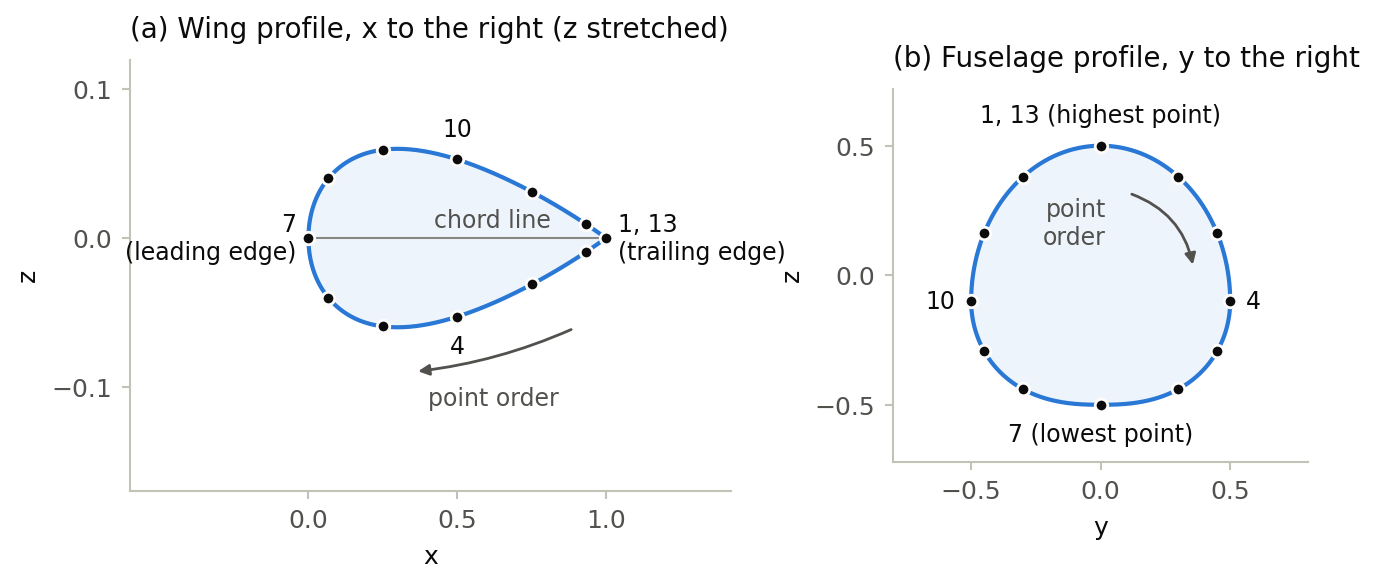
The following wing airfoil and fuselage profile are the ones shown in the figure. The parameterMap of the fuselage profile gives its widest points, points 4 and 10, the curve parameters of the widest points of a superellipse (see standardProfileType).
<profiles>
    <wingAirfoils>
        <wingAirfoil uID="NACA0012_points">
            <name>NACA 0012, 13 points</name>
            <pointList>
                <x>1;0.933;0.75;0.5;0.25;0.067;0;0.067;0.25;0.5;0.75;0.933;1</x>
                <y>0;0;0;0;0;0;0;0;0;0;0;0;0</y>
                <z>0;-0.0093;-0.0312;-0.0529;-0.0594;-0.0401;0;0.0401;0.0594;0.0529;0.0312;0.0093;0</z>
            </pointList>
        </wingAirfoil>
    </wingAirfoils>
    <fuselageProfiles>
        <fuselageProfile uID="FuselageProfile_points">
            <name>Fuselage profile, point list</name>
            <pointList>
                <x>0;0;0;0;0;0;0;0;0;0;0;0;0</x>
                <y>0;0.3;0.45;0.5;0.45;0.3;0;-0.3;-0.45;-0.5;-0.45;-0.3;0</y>
                <z>0.5;0.38;0.1615;-0.1;-0.2925;-0.4397;-0.5;-0.4397;-0.2925;-0.1;0.1615;0.38;0.5</z>
                <parameterMap>
                    <pointIndices>4;10</pointIndices>
                    <paramOnCurve>0.25;0.75</paramOnCurve>
                </parameterMap>
            </pointList>
        </fuselageProfile>
    </fuselageProfiles>
</profiles>Symmetry
A profile can be symmetric. In that case the profile is interpreted as being not closed and will be closed by mirroring it on the symmetry plane. For a fuselage profile, the first point then has to lie in the symmetry plane.