The class-shape transformation (CST) describes a profile by two analytical functions, one for the upper and one for the lower side. Instead of a list of points, a few parameters per side define a smooth profile with a well-defined leading and trailing edge. This makes the parameterization compact and well suited for design and optimization.
Coordinates
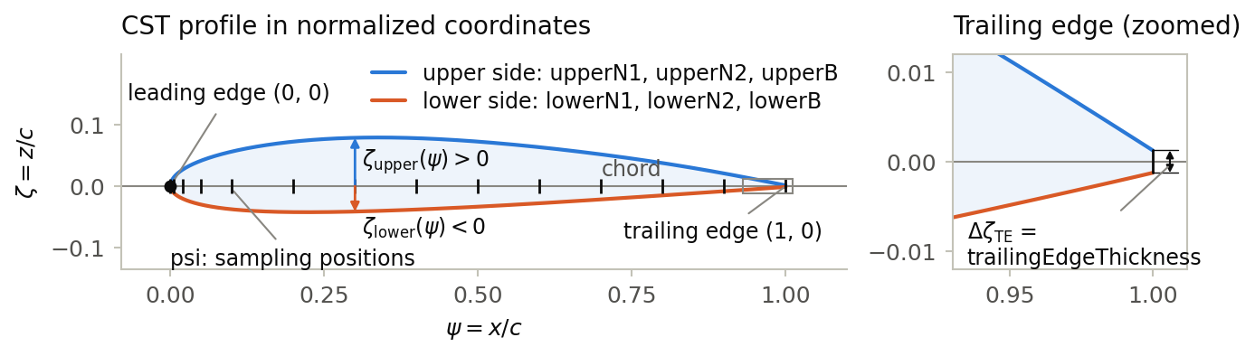
The profile is defined in coordinates normalized by the chord length c. ψ = x/c runs along the chord from the leading edge (ψ = 0) to the trailing edge (ψ = 1). ζ is the normalized coordinate normal to the chord (z/c for wing and rotor airfoils, y/c for nacelle profiles). The leading edge therefore lies at (0, 0) and the trailing edge at (1, 0). Size, position and orientation of the profile are defined where it is referenced, e.g. by the transformation of a wing element.
Upper and lower side
Each side is the product of a class function C and a shape function S, plus a linear term for the trailing edge thickness:
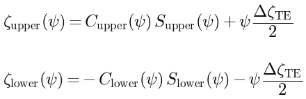
Both sides are parameterized independently: the upper side by upperN1, upperN2 and upperB, the lower side by lowerN1, lowerN2 and lowerB. Due to the minus sign in the equation of the lower side, positive lowerB coefficients place the lower side below the chord. A symmetric profile therefore has identical parameters for both sides. Note that this differs from the original notation by Kulfan, in which the coefficients of the lower side are usually negative.
Class function

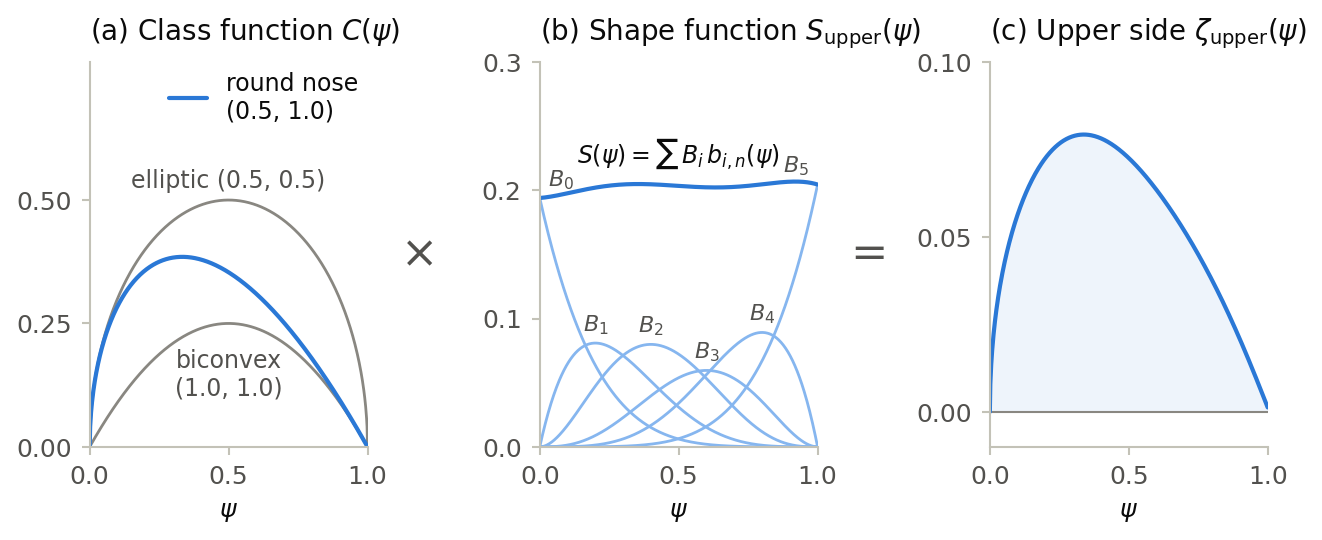
The class function defines the basic type of the profile. It is zero at the leading and at the trailing edge; the exponent N1 shapes the leading edge and N2 the trailing edge. Typical combinations are:
| N1 | N2 | Profile type |
| 0.5 | 1.0 | conventional airfoil with round leading edge and sharp trailing edge |
| 0.5 | 0.5 | elliptic profile, round at both ends |
| 1.0 | 1.0 | biconvex profile, pointed at both ends |
Shape function

The shape function scales the class function along the chord. It is a weighted sum of Bernstein polynomials whose weights Bi are the entries of upperB or lowerB, ordered from the leading to the trailing edge. The number of coefficients determines the polynomial degree n = (number of coefficients − 1); more coefficients allow more detailed shapes. Each coefficient acts mainly on one part of the chord:
-
The first coefficient B0 controls the leading edge. For N1 = 0.5 it defines the leading edge radius: RLE/c = B0²/2.
-
The last coefficient Bn controls the trailing edge. For N2 = 1.0 it defines the angle β between surface and chord at the trailing edge: tan β = Bn − ΔζTE/2.
-
The remaining coefficients shape the region between leading and trailing edge. Identical coefficients yield a constant shape function, i.e. the class function scaled by that value.
The following figure shows how class function and shape function combine to the upper side of the example below:
Trailing edge thickness
The optional trailingEdgeThickness (ΔζTE in the equations above) is the total thickness at the trailing edge relative to the chord. Half of it is added to each side, growing linearly from zero at the leading edge. If it is omitted, the trailing edge is sharp.
Sampling positions
The psi vector lists the positions at which a tool that needs discrete coordinates, e.g. for exporting a point list, evaluates the profile. It does not change the shape, which is defined for all ψ between 0 and 1. The values are given in ascending order from 0 to 1 and are typically denser near the leading edge, where the curvature is highest.
Example
The following wing airfoil approximates the NACA 2412 airfoil, including its finite trailing edge thickness. It is the profile shown in the figures above.
<wingAirfoil uID="NACA2412_CST">
    <name>NACA 2412 (CST)</name>
    <cst2D>
        <psi>0;0.005;0.02;0.05;0.1;0.2;0.3;0.4;0.5;0.6;0.7;0.8;0.9;1</psi>
        <upperN1>0.5</upperN1>
        <upperN2>1.0</upperN2>
        <upperB>0.1939;0.1974;0.231;0.1723;0.2176;0.2044</upperB>
        <lowerN1>0.5</lowerN1>
        <lowerN2>1.0</lowerN2>
        <lowerB>0.1516;0.1062;0.0926;0.0931;0.0704;0.0758</lowerB>
        <trailingEdgeThickness>0.0025</trailingEdgeThickness>
    </cst2D>
</wingAirfoil>Reference: B. M. Kulfan, "Universal Parametric Geometry Representation Method", Journal of Aircraft, Vol. 45, No. 1, pp. 142–158, 2008, doi:10.2514/1.29958.