A guide curve profile describes the shape of a guide curve independently of where the curve lies. Its points are given relative to the start and end point of the guide curve and to the size of the profiles. Several guide curves can therefore share one guide curve profile, also in segments of different size or in different components; the shape scales with the profiles.
Coordinates
For wings and fuselages, rY is the position along the straight line from the start point (0) to the end point (1) of the guide curve. rX and rZ are offsets from this line, as fractions of the chord length (wing) or height (fuselage) of the profiles at this position. rX is applied along the x-axis of the wing or the z-axis of the fuselage, unless the guide curve gives another rXDirection; rZ is applied normal to it and to the line. The exact construction is given for the guide curve (guideCurveType).
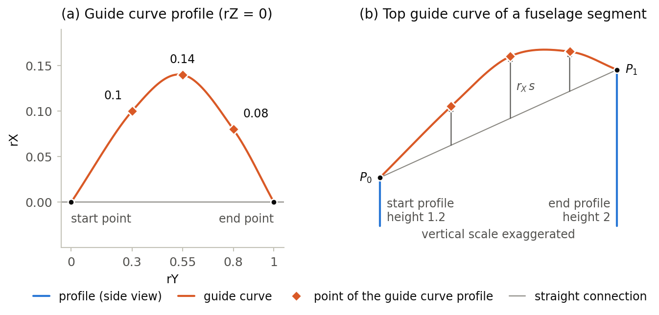
Figure (a) shows the guide curve profile of the example below in its own coordinates, figure (b) the guide curve it gives on top of a fuselage segment whose height grows from 1.2 to 2. Each point is lifted by rX times the local height, so the same value of rX gives a larger offset near the larger profile.
Points
-
The guide curve passes through all points, in the order of the list, i.e. with increasing
rY. -
Start and end point are not part of the list; they are given by the guide curve. The first point therefore has an
rYgreater than 0 and the last point anrYless than 1. -
At least one point is required. A single point with
rXandrZequal to 0 gives a straight guide curve.
For nacelles, the coordinates have a different meaning (nacelleGuideCurveType): rX runs from 0 at the start section to 1 at the end section, and the points are ordered with increasing rX.
Example
The first profile gives a straight guide curve. The second one is the profile shown in the figure: used for the top guide curve of a fuselage, it forms a canopy hump that rises by up to 14 % of the local height.
<guideCurves>
    <guideCurveProfile uID="GCP_straight">
        <name>Straight guide curve</name>
        <pointList>
            <rX>0</rX>
            <rY>0.5</rY>
            <rZ>0</rZ>
        </pointList>
    </guideCurveProfile>
    <guideCurveProfile uID="GCP_canopy">
        <name>Canopy hump</name>
        <pointList>
            <rX>0.1;0.14;0.08</rX>
            <rY>0.3;0.55;0.8</rY>
            <rZ>0;0;0</rZ>
        </pointList>
    </guideCurveProfile>
    ...
</guideCurves>