| nacelleGuideCurveType Complex Type |
Guide curve
Namespace: Empty
Schema: Empty

| Name | Occurrences | Description |
|---|---|---|
 All All | ||
 description description | [0, 1] | Description |
| fromZeta | Curve coordinate of the referenced section profile at which the guide curve shall start. Valid values are in the interval -1,..,1. | |
| guideCurveProfileUID | UID of the guide curve profile | |
| name | Name | |
| startSectionUID | UID of the start section | |
| toZeta | Curve coordinate of the profile following the referenced section profile. It defines where the guide curve ends. Valid values are in the interval -1,..,1. |
| Name | Type | Required | Description |
|---|---|---|---|
 externalDataDirectory externalDataDirectory |  string string | ||
| externalDataNodePath | string | ||
| externalFileName | string |
The following figure shows the basic setup of the guide curves. They always start at a given ζ-position (fromZeta) on the profile of the specified start section (startSectionUID) and end at the ζ-position (toZeta) on the profile of the subsequent section. The relative coordinates of the guide curves are specified in cpacs/vehicles/profiles/guideCurves and referenced via its uID.
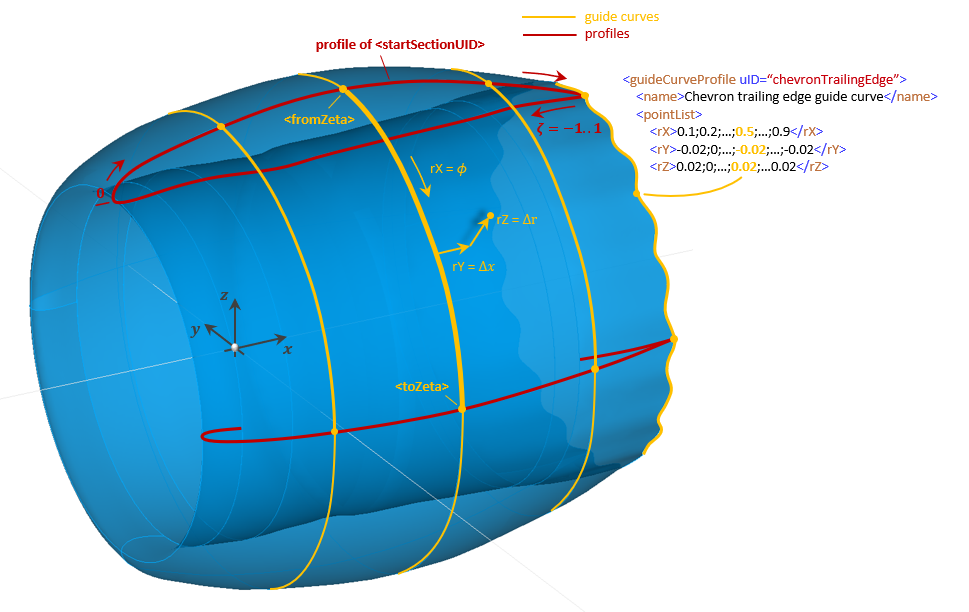
Note: Guide curves and profiles must result in a valid curve network.
The guide curve points are interpreted as (Δr and Δx) offsets from a cubic polynomial. This polynomial serves as a baseline for guide curves between segments located on different radial positions with smooth transitions:
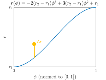
Note: Currently, the nacelles do not have an explicit guide curve type but employ the standard guide curve definition, which is used in wings and profiles. Therefore, the parameters have a different meaning:
| Standard guide curve parameter | Nacelle guide curve equivalent | Description |
| rX | φ | Independent variable normalized to [0,1] |
| rY | Δx | Orthogonal offset (translation in x-direction) |
| rZ | Δr | Radial offset |