| controlSurfaceBorderTrailingEdgeType Complex Type |
Inner/outer border of the control surface.
Namespace: Empty
Schema: Empty
 Base Type
 UsagesChildren
| Name | Occurrences | Description |
|---|---|---|
 All All | ||
 airfoil airfoil | [0, 1] | Reference to the airfoil contour |
| etaLE | Relative spanwise inner/outer position of the leading edge of the control surface. Reference is eta/xsi from the parent. | |
| etaTE | [0, 1] | Relative spanwise inner/outer position of the trailing edge of the control surface. Reference is eta/xsi from the parent. Defaults to 'etaLE'. |
| innerShape | [0, 1] | Hollow shape inside the leading edge |
| leadingEdgeShape | [0, 1] | Shape of the leading edge of the control surface |
| xsiLE | Relative chordwise inner/outer position of the leading edge of the control surface. Reference is eta/xsi from the parent. |
Attributes| Name | Type | Required | Description |
|---|---|---|---|
 externalDataDirectory externalDataDirectory |  string string | Directory of the external data file | |
| externalDataNodePath | string | Path of the node inside the external data file | |
| externalFileName | string | Name of the external data file |
RemarksDefinition of the inner/outer border of the control surface.
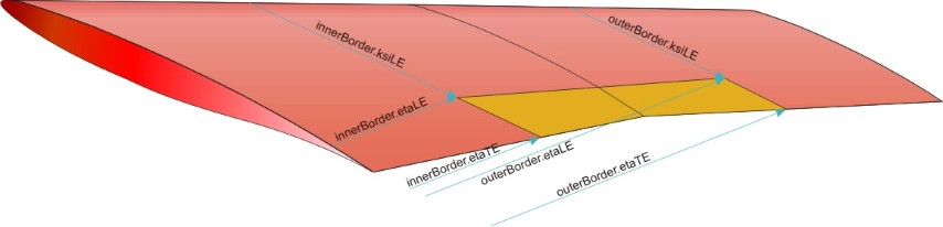
The position on the planform of the control surface is defined by defining the eta/xsi coordinates of the inner/outer and forward/rear border. The eta/xsi coordinates refer to the parent.
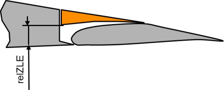
In addition, optionally, the airfoil shape of the control surface can be defined closer. For the trailing edge device this is done at 'leadingEdgeShape', for the spoiler 'relHeightLE' is used and for the leading edge devices 'hollow'. If an exact control surface airfoil definition should be used, outerShape->airfoils can be used.
Please find below an example for the definition of the planform of a trailing edge device. Other controlsurfaces are similar.