| componentSegmentType Complex Type |
ComponentSegment of the wing.
Namespace: Empty
Schema: Empty
 Base Type
 UsagesChildren
| Name | Occurrences | Description |
|---|---|---|
 All All | ||
 controlSurfaces controlSurfaces | [0, 1] | Control surfaces |
| description | [0, 1] | Description |
| fromElementUID | Reference to the element from which the componentSegment shall start | |
| name | Name | |
| path | [0, 1] | Deflection path of componentSegments (e.g. used for trimmable HTPs) |
| structure | [0, 1] | Structural layout |
| toElementUID | Reference to the element from which the componentSegment shall end | |
| wingFuelTanks | [0, 1] | Fuel tanks |
| wingFuselageAttachments | [0, 1] | Attachments between the componentSegment and a fuselage |
| wingStructuralMounts | [0, 1] | Structural mounts |
| wingWingAttachments | [0, 1] | Attachments between the componentSegment and another wing |
Attributes| Name | Type | Required | Description |
|---|---|---|---|
 externalDataDirectory externalDataDirectory |  string string | Directory of the external data file | |
| externalDataNodePath | string | Path of the node inside the external data file | |
| externalFileName | string | Name of the external data file | |
| uID | ID | Yes | UID |
RemarksWithin componentSegments the wing structure, the control surfaces, the wing fuel tanks and the wingFuselageAttachment is defined by using relative coordinates.
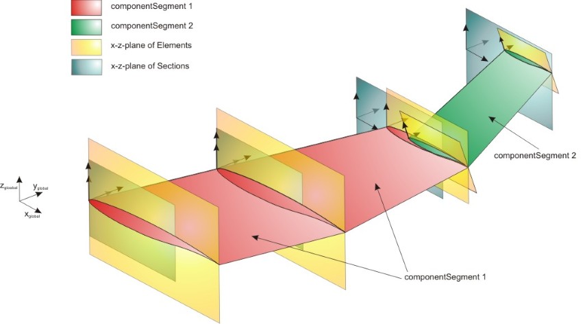
A componentSegment is defined in the same way as segments: from one cross section (sections->elements) to another. Compared to segments one componentSegment can can start and end at elements that are not consecutive. Therefore that one componentSegment can be the combination of several segments. Each wing has at least one componentSegment (from root to tip). The maximal number of componentSegments equals the number of segments (each segment is defined as one componentSegment). This also implies that each segment can only be part of one componentSegment.
In principal a componentSegment can combine any number of segments. But if in one section two elements are defined, the componentSegment has to start/end there as no well-defined relative coordinates can be defined if steps in the wing occur.
An example for wing componentSegments can be found in the picture below:
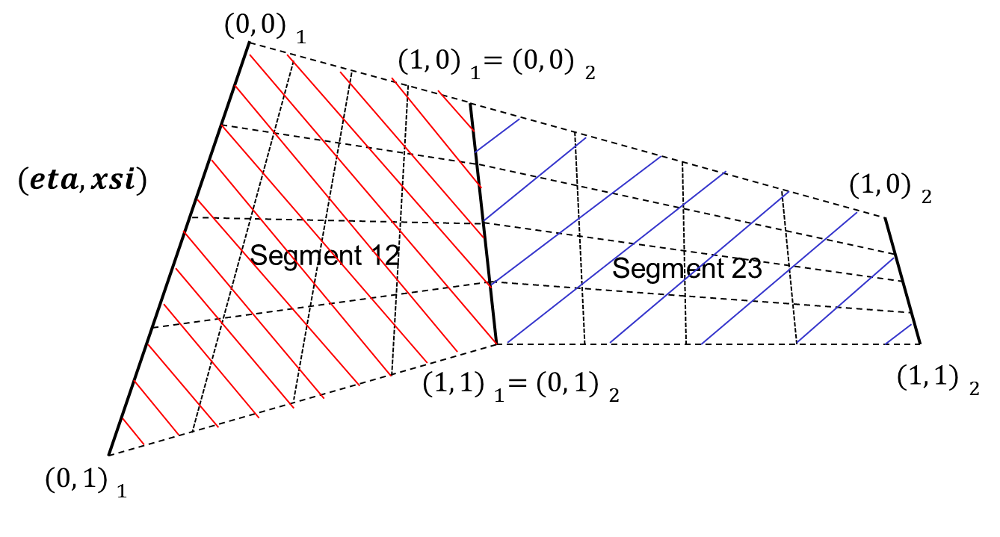
Within componentSegments a relative spanwise coordinate (eta) and a relative chordwise coordinate (xsi) is defined. Those coordinates are used for the definition of e.g. wing structures and control surfaces. there are two types of eta xsi coordinates. Segment (eta, xsi) coordinates define the relative local coordinate system for a segment ranging from (0,0) to (1,1).
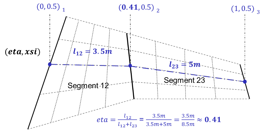
The eta xsi coordinates for a component segment are based on the segment eta xsi planes. As a reference length for the component segment eta coordinate the mid chord lines of all the segments are used. The beginning of this line at from-element equals eta = 0, while the end of this line at the to-element equals eta = 1. All wing positions that lie on the same element (segment border) have the same eta coordinate. The points in between two elements are defined by the iso xsi lines of the segment eta xsi space. An example for the definition of the relative axes can be found in the picture below:
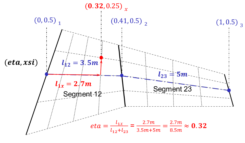
In order to calculate the global coordinates of a component segment eta xsi point one first has to calculate the eta point on the xsi iso line of (xsi=0.5), and then walk along the iso eta lineof the segment.
An example for determining the a component eta xsi point can be found in the picture below: