| rotorBlades Element |
Rotor blade elements
Namespace: Empty
Schema: Empty
| Name | Occurrences | Description |
|---|---|---|
| [1, *] | Rotor blade geometries are defined using the same data structure as wings (wingType). But in order to be compatible with the other rotor blade related types (e.g. rotorType, rotorHubType, rotorHubHingeType) there are some additional conventions/requirements regarding the definition and orientation of rotorBlade geometries: see remarks. |
| Name | Type | Required | Description |
|---|---|---|---|
RotorBlades type, containing all the rotor blade gometry definitions of an rotorcraft model.
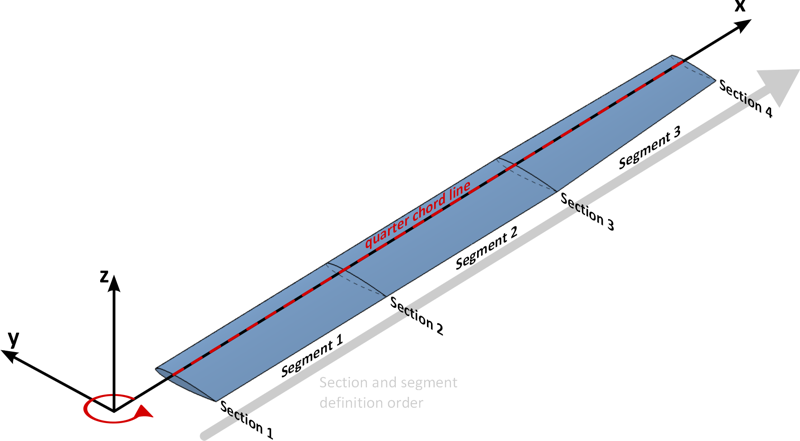
Rotor blade geometries are defined using the same data structure as wings (wingType). But in order to be compatible with the other rotor blade related types (e.g. rotorType, rotorHubType, rotorHubHingeType) there are some additional conventions/requirements regarding the definition and orientation of rotorBlade geometries:
- Rotor blades should be positioned relative to the global z-axis the way they will be positioned to the rotor shaft (when blade azimuth=0deg).
- The global x-axis should be used as radial axis (usually the quarter chord line of the rotor blade coincides to a great extent with the x-axis of the rotor blade coordinate system).
- All sections should be positioned in the positive x halfspace.
- Segments should connect sections with ascending x coordinates.
- Airfoils defined in the rotorAirfoils node should be used instead airfoils from the wingAirfoils node.
