4.1. CPACS coordinate system
The CPACS coordinate system is the global reference coordinate system of a CPACS dataset. It is a right-handed Cartesian coordinate system with the axes x, y and z. All other coordinate systems are defined relative to it: the aerodynamic coordinate system (section 4.2) and the local coordinate systems of components (section 4.3).
Typically, an aircraft is placed in the CPACS coordinate system so that its axes follow the directions in the table below, often with the origin at the nose. This placement is common practice rather than a requirement: a vehicle that is shifted or rotated against these directions is valid as well. Tools should therefore evaluate the data in the CPACS coordinate system rather than assume a particular body axis, such as a fuselage axis through nose and tail.
| Axis | Typical direction | Description |
| x | to the rear | from the nose to the tail |
| y | to the right | from the plane of symmetry to the right wing tip |
| z | upwards | from the bottom to the top of the aircraft |
4.2. Aerodynamic coordinate system
This part is needed for aerodynamic data only; readers working with other data can skip it.
The aerodynamic coefficients of an aircraft, i.e. the force coefficients <cd>, <cs>, <cl> and the moment coefficients <cmd>, <cms>, <cml> of the aerodynamic maps (aeroPerformanceMapType), their increments and their derivatives, are given in the aerodynamic coordinate system. Its axes follow the free stream: the d-axis (drag) points in the direction of the free stream, i.e. to the rear, the l-axis (lift) upwards perpendicular to it, and the s-axis (side force) to the right. The aerodynamic coordinate system is turned against the CPACS coordinate system by the angle of attack α and the sideslip angle β. The coefficients are therefore neither body-fixed nor given along the CPACS axes.
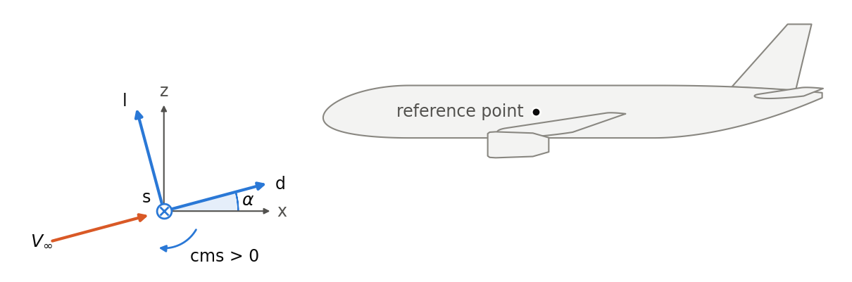
The side view shows an aircraft from the left with the free stream V∞ coming from below. The angle of attack α turns the axes d and l out of the CPACS axes x and z about the y-axis, which coincides with the s-axis here.
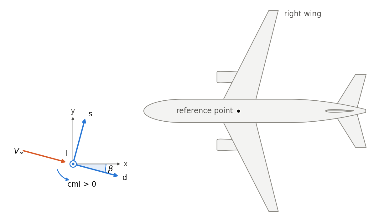
The top view shows the free stream coming from the right. The sideslip angle β turns the axes d and s out of the CPACS axes x and y about the l-axis, which coincides with the z-axis here.
In the CPACS coordinate system, the unit vectors of the three axes are:
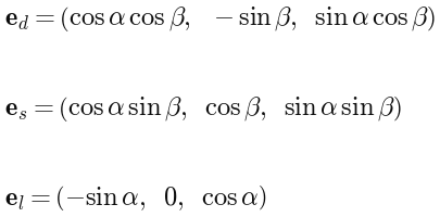
Turning the free stream first by β about the l-axis and then by α about the y-axis brings it onto the x-axis. Hence, α is the angle between the x-axis and the projection of the free stream onto the x-z plane, and β is the angle between the free stream and the x-z plane. The l-axis always lies in the x-z plane.
-
The angle of attack α and the sideslip angle β are positive about their axes (right-hand rule) from the free stream to the CPACS axes. A positive α means a free stream from below, a positive β a free stream from the right, i.e. onto the right-hand side of the cockpit.
-
Both angles refer to the CPACS axes, not to the fuselage. For a vehicle that is rotated in the CPACS coordinate system, α = 0 does not mean a free stream along the fuselage.
-
The force coefficients are positive along their axes:
<cd>in the direction of the free stream,<cl>upwards and<cs>to the right. -
The moment coefficients are positive about their axes by the right-hand rule: a positive rolling moment
<cmd>lifts the right wing, a positive pitching moment<cms>raises the nose, and a positive yawing moment<cml>turns the nose to the left. -
The moments refer to the moment reference point of the model (
.../model/reference/point), not to the center of gravity. All coefficients are normalized with the reference area (.../model/reference/area), and all three moment coefficients in addition with the same reference length (.../model/reference/length). The equations are given inaeroPerformanceMapType.
4.3. Local coordinate systems via parentUID and transformation
Geometric components such as fuselages, wings, engines or fuel tanks are each defined in a local coordinate system, which their <transformation> places in the coordinate system of their parent. The parent is set with the optional <parentUID> element, which references the @uID of another component. In this way, the user builds the hierarchy of the vehicle, e.g. attaches an engine to a wing or to the fuselage, instead of having it prescribed by the XML tree.
-
A component without
<parentUID>is placed by its transformation directly in the CPACS coordinate system. Any number of components may be without<parentUID>; each of them is the top of its own hierarchy. -
A component with
<parentUID>follows only the translation of its parent. WithrefType="absLocal"of its translation, which is the default, the translation is measured from the origin of the parent coordinate system along the CPACS axes; the rotation and scaling of the parent do not apply. WithrefType="absGlobal", the translation is given in the CPACS coordinate system, as for a component without parent. -
The
@refTypeonly has a meaning for a component with<parentUID>and is omitted elsewhere. -
Parts that are nested in another node by the XML structure, e.g. the sections and elements of a wing or a deck in its fuselage, have that node as parent and need no
<parentUID>.
The equations and an example are given in transformationType. The @refType attribute belongs to the translation, and the following table summarizes where the translation of a component refers to:
<parentUID> not set | <parentUID> set | |
refType="absLocal" (default) | CPACS coordinate system | origin of the parent |
refType="absGlobal" | CPACS coordinate system | CPACS coordinate system |
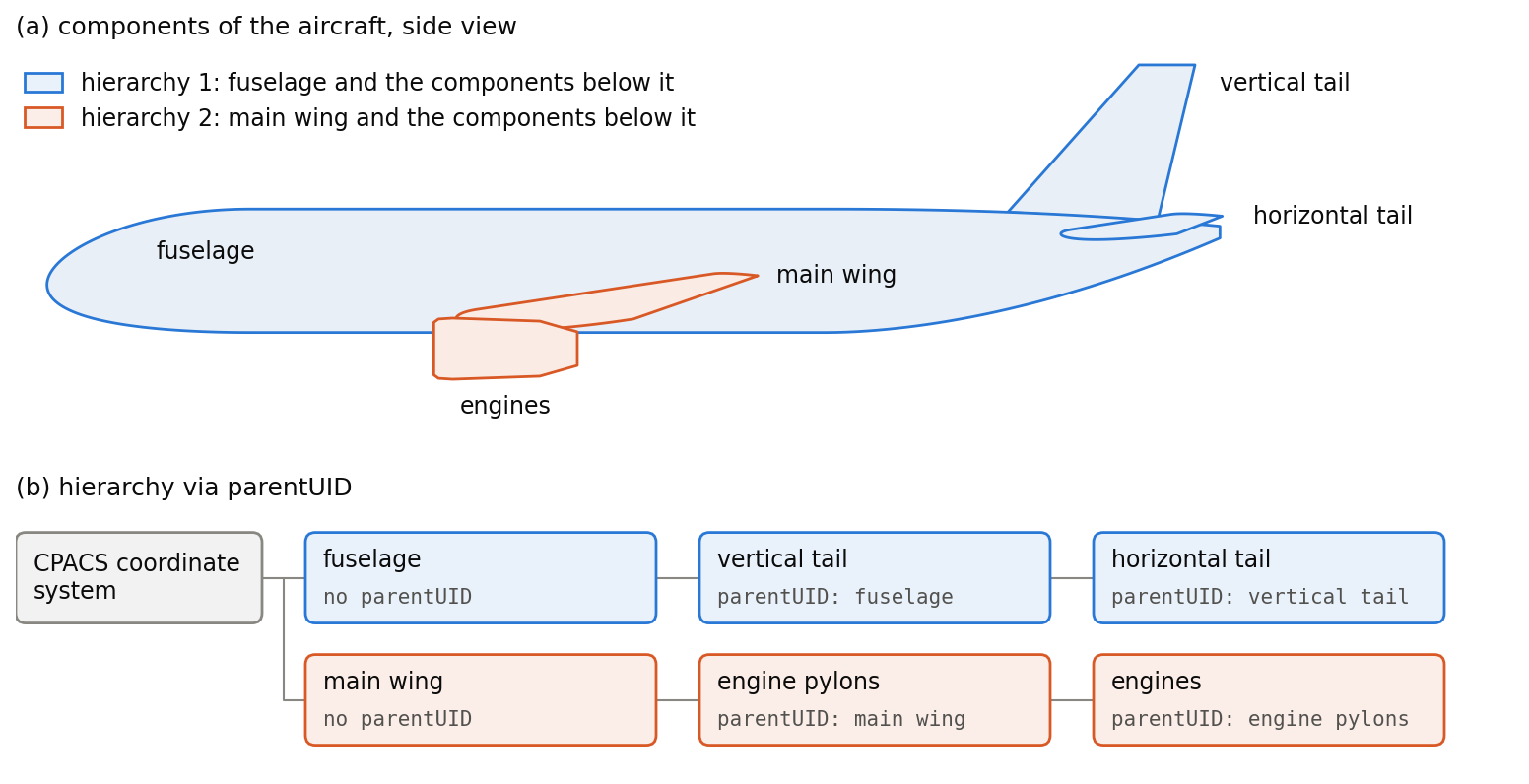
The figure shows an aircraft with two hierarchies. The fuselage and the main wing have no <parentUID>, so that each of them is placed directly in the CPACS coordinate system. The vertical tail references the fuselage, the horizontal tail the vertical tail, the engine pylons the main wing, and the engines the engine pylons. Translating the main wing therefore also moves the engine pylons and the engines, but not the fuselage or the tail. Equally, the main wing could reference the fuselage; it would then follow the translation of the fuselage as well.